Quantcast
Channel: Power Substation - Technical Articles | EEP - Electrical Engineering Portal
Viewing all 279 articles
Browse latest View live

6 Simple Rules to Ensure Substation Safety

$
0
0
6 Simple Rules to Ensure Substation Safety

6 Simple Rules to Ensure Substation Safety

Importance of safety protection

Another extremely important substation engineering aspect is associated with safety protection. It is fair to say that safety is always a No. 1 priority in substation design, operation and maintenance.

Unlike the case where a higher reliability required a larger investment, we can’t put a price tag on safety since there is no such thing like working conditions being more or less safe. It should always be 100% safe to work at or visit the substation.

There are numerous laws, rules, codes, etc. governing safety requirements; of the most important being IEEE Standard C2-2012. 2012 National Electrical Safety Code®” (NESC®)

The main mission of all these regulations is safeguarding of personnel from hazards arising from the installation, maintenance or operation of substation equipment.

Safety standards contain requirements for:

  • Enclosure of electrical equipment
  • Rooms and spaces
  • Illumination
  • Floors, floor openings, passageways, stairs
  • Exits
  • Installation of equipment:
  • Specific rules for installation of all typical substation equipment

All these measures are based on common sense and the goal to provide a safe environment for substation personnel.


6 rules to provide substation safety

Rule no. 1 (clearance)

Enough clearance from energized parts should be provided to avoid accidental contact with them. If that can’t be met, live parts should be guarded or enclosed.


Rule no. 2 (minimum height)

A minimum height from the ground to any ungrounded part of an electrical installation should be 8’-6”, so a person staying on the ground can’t touch a substation element or its part which may become energized accidentally. For example, the bottom of a post insulator supporting an energized bus does not normally have any potential.

However, if bus flashover to the ground over insulator occurs, touching the bottom of the insulator may become unsafe. That’s why an 8’-6” distance from the bottom of insulator to the ground should be provided.

Rule no. 3 (illumination…)

There should be sufficient illumination for personnel to clearly see their surroundings and perform any work safely. Required illumination levels are specified in NESC® [1].


Rule no. 4 (passageways…)

All passageways and stairs should be wide enough for personnel to navigate them safely, adequate railing should be provided, and floor openings should have guard rails.


Rule no. 5 (evacuation routes)

Exits should be clearly marked and evacuation routes should be free from obstructions. Depending on the function of the building (for example, control house), it may require several exits to avoid personnel being trapped during equipment fault, fire, etc.


Rule no. 6 (grounding, as always)

All substation metallic structures, fences, and equipment tanks should be connected to a station ground grid which should be designed to ensure that step and touch potential values are lower than the ones stipulated in the applicable standards.

Reference: Fundamentals of Modern Electrical Substations; Part 3: Electrical Substation Engineering Aspects by Boris Shvartsberg, Ph.D., P.E., P.M.P.


Location of Current Transformers in HV Substation

$
0
0
Siemens High Voltage Instrument Transformers

Siemens High Voltage Instrument Transformers

Power flow

Current transformers are used for protection, instrumentation, metering and control. It is only the first function that has any bearing on the location of the current transformer.

Ideally the current transformers should be on the power source side of the circuit breaker that is tripped by the protection so that the circuit breaker is included in the protective zone.

In many circuits the power flow can be in either direction and it then becomes necessary to decide which location of fault is most important or likely and to locate the current transformers on the side of the circuit breaker remote from those faults. In the case of generator (and some transformer) circuits it is necessary to decide whether the protection is to protect against for faults in the generator or to protect the generator against system faults.

Current transformers can often be located in the generator phase connections at the neutral end and will then protect the generator from the system faults and to a large degree give protection for faults in the generator.

When current transformers can be accommodated within the circuit breaker, they can in most cases be accommodated on both sides of the circuit breaker and the allocation of the current transformers should give the desired overlapping of protective zones.

With some designs of circuit breaker the current transformer accommodation may be on one side only and it may be necessary to consider the implications of the circuit breaker position in the substation before deciding on the electrical location of the current transformers.

CT’s mounted inside the CB (CT’s on both sides of CB)

CT’s mounted inside the CB (CT’s on both sides of CB)


CT’s are on the circuit side of the CB

CT’s are on the circuit side of the CB


However the risk of a fault between the current transformers and the circuit breaker and within the circuit breaker itself is very small and so the economics of accommodating the current transformers may have an important influence on their location.

Where separate current transformer accommodation has to be provided, the cost of separately mounted current transformers and also the extra substation space required almost always results in them being located only on one side of the circuit breaker. In practice this is generally on the circuit side of the circuit breaker.

This follows metalclad switchgear practice where this is the easiest place to find accommodation, and is also the optimum position when bus zone protection is required.

Often it may be possible to accommodate current transformers on the power transformer bushings or on through wall bushings. When this is done it is usually for economic reasons to save the cost of, and space for, separately mounted current transformers.

Transformer mounted current transformers have minor disadvantages in that a longer length of conductor and, more especially, the bushing is outside the protected zone, and in the event of the transformer being removed then disconnections have to be made to the protective circuits.

Note that the arrangement of the individual current transformers within a unit should preferably be arranged that any protective zones overlap and that current transformers for other functions are included within the protected zone.

Under by-pass conditions (where this is provided) the circuit is switched by the bus coupler circuit breaker.

The location of the current transformers is determined by whether the protective relaying and current transformers are provided by the bus coupler circuit, or whether the protective relaying and current transformers of the circuit are used with the tripping signal being routed to the bus coupler circuit breaker during by-pass. If the latter method is used then the current transformers must be separately mounted on the line side of the by-pass isolator.

Advantages

The advantage of this method is that the circuit protection is unchanged to the possibly inferior protection of the bus coupler circuit. On the other hand the circuit would have to be taken out of service to work on the current transformers.

The need for continued metering of the by-passed circuit needs also to be considered.


Possible locations of current transformers

Figures 1 (a), (b) and (c) show possible locations of current transformers in a portion of mesh substation.


Arrangement (a)

In arrangement (a) the current transformers are summed to equate to the feeder current and to operate the circuit protection.

Mesh Circuit CT’s - Arrangement (a)

Mesh Circuit CT’s – Arrangement (a)


The protection also covers a portion of the mesh and, with overlapping current transformers as shown, the whole mesh is included in discriminative protective zones. Because the feeder current may be significantly smaller than the possible mesh current, the ratio of the mesh current transformers may be too high to give the best feeder protection.


Arrangement (b)

In arrangement (b) the current transformers are in the feeder circuit and so their ratio can be chosen to give the best protection.

Mesh Circuit CT’s - Arrangement (b)

Mesh Circuit CT’s – Arrangement (b)


However there is now no discriminative protection for the mesh. Note that the current  transformers can be located either inboard or outboard of the feeder isolator, the choice being dependent on the ease of shutting down the feeder circuit and the undesirability of opening the mesh if maintenance of the current transformer were required.


Arrangement (c)

The arrangement shown in (c) is a combination of (a) and (b) with, if necessary, different ratio current transformers in the feeder circuit. This arrangement however requires three sets of current transformers as opposed to two and one in arrangements (a)and (b).

Mesh Circuit CT’s - Arrangement (c)

Mesh Circuit CT’s – Arrangement (c)


Similar arrangements are possible with breaker-and-a-half substations with the slight difference that at the end of the diameter the protection becomes protection for the busbar instead of a feeder. All the diameter currents are summed for the bus zone protection.

Reference: Substation design/application guide – V AYADURAI BSC, C.Eng, FIEE Engineering Expert

Why is Continuous On-line Monitoring of Partial Discharge in the Switchgear Necessary?

$
0
0
Why is Continuous On-line Monitoring Partial Discharge in the Switchgear Necessary?

Why is Continuous On-line Monitoring Partial Discharge in the Switchgear Necessary? (on photo: 11kV voltage transfromer spout failure in progress – Located by Partial Discharge survey; by highvoltagesolution.com)

What’s the condition of your switchgear?

Not sure?

You know that periodical maintenance test like partial discharge test can still leave switchgear in virtually unknown condition. Insulation defects and deterioration may very well develop in service within maintenance cycle.

These defects are often not detectable with traditional off-line tests and yet, traditionally, on-line or off-line partial discharge tests have been performed on a periodic basis commonly twice a year.

Think this is often enough?

Advantages over periodic partial discharge (PD) testing

Continuous PD monitoring has the following advantages over periodic PD testing:

1. Periodic on-line PD test could miss significant PD activities since PD activities vary by time. On-line continuous monitoring eliminates the inherent flaw of interval-based testing.

2. Trending of PD activity is one of the most important parameters for predictive diagnostics. Periodic tests will not be able to provide sufficient information for diagnostics based on trending.

3. On-line monitoring provides more accurate information than off-line testing since off-line testing conditions can differ greatly from real operating conditions.

4. Continuous on-line monitoring effectively reduces labor costs. In addition, the PD data saved in the instrument can be accessed anytime, anywhere with modern communication means.

Partial discharge test performed on site

Partial discharge test performed on site (photo credit: epowerplus.com)

Degradation of Insulation in Switchgear

Electrical insulation is subjected to electrical and mechanical stress, elevated temperature and temperature variations, and environmental conditions especially for outdoor applications.

In addition to normal operating conditions, there are a host of other factors that may trigger accelerated aging or deterioration of insulation.

Switching and lightning surges can start ionization in an already stressed area. Mechanical strikes during breaker operation can cause micro cracks and voids. Excessive moisture or chemical contamination of the surface can cause tracking.

PD Between Bus and Cubicle Wall

PD Between Bus and Cubicle Wall


Any defects in design and manufacturing are also worth mentioning. Both normal and accelerated aging of insulation produce the same phenomenon in common – Partial Discharge (PD).

Partial discharge (PD) is a localized electrical discharge that does not completely bridge the electrodes. PD is a leading indicator of an insulation problem. Quickly accelerating PD activity can result in a complete insulation failure.

Partial discharge mechanism

PD mechanism can be different depending on how and where the sparking occurs:

  1. Voids and cavities are filled with air in poorly cast current transformers, voltage transformers and epoxy spacers. Since air has lower permittivity than insulation material, an enhanced electric field forces the voids to flashover, causing PD. Energy dissipated during repetitive PD will carbonize and weaken the insulation.
  2. Contaminants or moisture on the insulation induce the electrical tracking or surface PD. Continuous tracking will grow into a complete surface flashover.
  3. Corona discharge from sharp edge of a HV conductor is another type of PD. It produces ozone that aggressively attacks insulation and also facilitates flashover during periods of overvoltage.


Reference:  Predictive Diagnostics for Switchgear – EATON

Arriving at the scene of a power substation fire. What to do?

$
0
0
Arriving at the scene of a power substation fire. What to do?

Arriving at the scene of a power substation fire. What to do? (on photo: Sammamish Substation fire – The burning mineral oil inside the high voltage transformer; via Puget Sound Energy/Flickr)

To contact utility personel

Power substations contain transformers, large quantities of oil, energized electrical equipment and, in some cases, cylinders of compressed gas. Some of the oil may contain polychlorinated biphenyls (PCBs).

On arriving at a substation fire, normally you should first call for firefighters and they should hook up and stand ready to protect adjacent properties. Utility personnel will tell firefighters when the substation has been made electrically safe. Firefighters can then proceed to put out the fire with conventional firefighting equipment.

Most substations are unattended, although an automatic signal system should summon a utility representative when an emergency develops. If a utility representative is not present when the firefighters arrive, the utility must be contacted to make sure one has been dispatched.

Most utility personnel are familiar with the substations they service. They are trained in the use of the specialized station firefighting apparatus and can identify the areas that are electrically safe.


Equipment in substation susceptible to fire:

Let’s go through the most common electrical equipment susceptible to the fire and see what happens:

  1. Transformers
  2. Conservators
  3. Explosion vents
  4. Porcelain bushings
  5. Overhead structures
  6. Control cables
  7. Cable trenches
  8. Circuit breakers
  9. Capacitors
  10. Substation Ground Grids

1. Transformers

Flames shoot high out of a Georgia Power substation transformer

Flames shoot high out of a Georgia Power substation transformer


There are several hazards to be aware of when fighting transformer fires. As you already know, transformers are devices used to step-up or step-down voltages. They usually contain large volumes of insulating oil which, of course, is combustible and has a flash point of 145°C. Some of this oil may contain PCBs.

A transformer consists of an iron core on which are placed two or three coils of conductors. By varying the number of turns on the coils, the voltage can be changed. The turns on the coils need to be insulated from each other to withstand the voltages. This insulation may be combustible.

For both cooling and insulating purposes, transformers are placed in large metal tanks. Further refinements can include pumps, fans, radiators or a large tank called a conservator, at the top of the main transformer tank which also contains oil.

Usually it is possible to extinguish transformer fires before all the oil has been consumed, thereby saving adjacent equipment from damage.

Go back to Index ↑


2. Conservators

Oil transformer conservator

Oil transformer conservator (photo credit: Tom Law via Flickr)


These are simply large tanks located at the top of transformers to allow for expansion and contraction of oil when the transformer is carrying electricity. There will be no large build up of pressure, but if one of these tanks were ruptured, it could release a large supply of fuel.

Go back to Index ↑


3. Explosion Vents

These are large vertical pipes with rupturable discs fitted to the transformer tops which are intended to vent pressure in the event of an internal transformer fault. They are unlikely to be a hazard to the people fighting a fire.

Go back to Index ↑


4. Porcelain Bushings

An oil-impregnated paper (OIP) bushing failure on the 400-kV, 100-MVAR reactor caused this reactor fire

An oil-impregnated paper (OIP) bushing failure on the 400-kV, 100-MVAR reactor caused this reactor fire (photo credit: tdworld.com)


The function of these bushings is to let the high-voltage transformer connection pass through the grounded metal tank without energizing it. Typically they contain the same insulating material found in transformers – paper and oil.

When subjected to high temperatures, the porcelain material can explode. This could result in flying projectiles and more oil as fuel for the fire. Be alert!

Go back to Index ↑


5. Overhead Structures

Overhead structure fire

Overhead structure fire (photo credit: Puget Sound Energy via Flickr)


Metal structures are often built over the top of electrical equipment to support insulators and high-voltage conductors. These structures will sag and eventually collapse when subjected to high temperatures.

Apart from the obvious hazards, such collapses could also result in breaking the transformer bushings with the consequences described above.

Go back to Index ↑


6. Control Cables

Control cables attached to large power transformers carry low voltage electricity for controlling cooling fans, pumps and motors. They usually become isolated if faulted.

Go back to Index ↑


7. Cable Trenches

Cable trenches carry the control cables mentioned above. In the event of a substation fire, cable trenches can carry transformer oil that may have leaked from a burning transformer or a broken porcelain bushing. Thus, a fire can be carried to adjacent equipment fairly readily.

Go back to Index ↑


8. Circuit Breakers

HV SF6 circuit breakers and  current transformers

HV SF6 circuit breakers and current transformers (photo credit: jcmiras.net)


These are large switches. Some types of circuit breakers are equipped with porcelain bushings and combustible oil whose hazards are described above.

Go back to Index ↑


9. Capacitors

HV capacitor banks

HV capacitor banks (photo credit: wisegeek.com)


Capacitors are located in some, but not all substations. A capacitor bank is comprised of a number of small units measuring approximately 25 cm x 45 cm x 60 cm (10 inches x 18 inches x 24 inches).

There are three main hazards that firefighters should be aware of:

  1. The individual capacitors are sealed units which could explode when heated.
  2. Some of the capacitors contain polychlorinated biphenyls (PCBs) which can be hazardous to your health and the environment. In the event of a spill, extreme caution should be exercised. Provincial environmental guidelines must be followed.
  3. Capacitors can store lethal amounts of electricity even with the power off. In the event of a fire, utility personnel would, as soon as practicable, make them safe to handle.

Firefighters in such a situation must take every precaution necessary to protect themselves and all members of the public present. Again, all provincial environmental guidelines must be adhered to.

Go back to Index ↑


10. Substation Ground Grids

An extensive grounding grid system is located under the gravel in all utility substations. Its function is to protect personnel from high-voltage levels during fault conditions on the transmission lines outside the substations.

For example, should lightning strike one of the utility’s lines, it could cause an insulator flashover at the station which would raise the ground voltage several thousand volts. Under normal circumstances, personnel would not be exposed to any danger because the grounding grid would distribute the voltage over a wide area.

Metal ladders must not be placed against a substation fence or otherwise used in fighting substation fires. Metal tap rules, extension cords and other metal objects can also create a hazard and are not permitted in utility substations.

The gravel covering substation property serves two vital functions:

  1. It insulates people from the grounding grid.
  2. In a fire,it cools down oil which may flow from transformers or other electrical equipment.

Go back to Index ↑

Reference: Electrical Safety Handbook for Emergency Personnel – NB Power Health and Safety Department

Microprocessor and conventional secondary systems compared

$
0
0
Microprocessor and conventional secondary systems compared

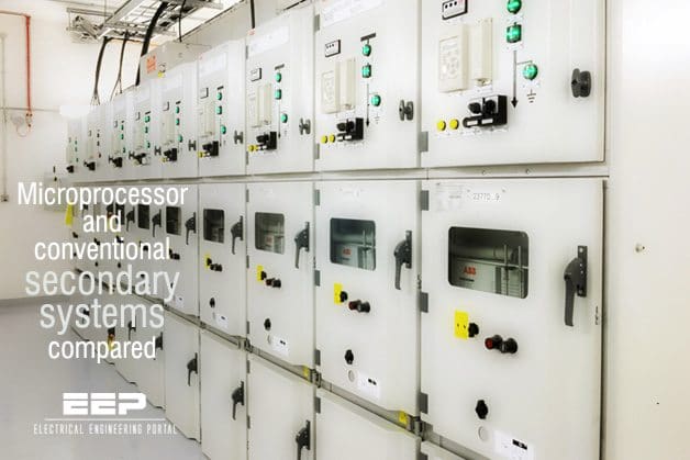
Microprocessor and conventional secondary systems compared (on photo: ABB’s Unigear 11kV switchgear panels)

Reliable operation of the primary system

Secondary systems are all those facilities needed to ensure reliable operation of the primary system, e.g. a high voltage substation. They cover the functions of controlling, interlocking, signalling and monitoring, measuring, counting, recording and protecting.

With conventional secondary systems, the various functions are performed by separate devices (discrete components) which mostly work on the analogue principle and as a rule are of varying sophistication.

Old technology

The resulting situation is as follows:

  1. Each task is performed by devices employing different technologies (electromechanical, electronic, solid-state or microprocessor-based).
  2. These discrete devices may require many different auxiliary voltages and power supply concepts.
  3. The links between the devices and with the switchgear require a great deal of wiring or cabling and means of matching.
  4. The information from the switching apparatus has to be applied separately to numerous inputs for protection, control, interlocks etc., so monitoring the interfaces is complicated.
  5. Checking the performance of the individual devices is accompanied by more difficult verification of overall performance.

With the new control technology for switching installations, the emphasis is on the system and its function as a whole. Digital methods are employed for the respective functions, using programmable modules based on microprocessors.

9 new technology features

The distinguishing features of the new technology are:

  1. Use of identical device components or combined devices based on microprocessors for the various tasks or functions.
  2. Standardized power supply and supply concept.
  3. Serial data transfer minimizes wiring (bus technique).
  4. Fibre optic cables are used near the process to reduce the cost of established adequate electromagnetic compatibility.
  5. Composite use made of data from the switchgear.
  6. Self-diagnosis with continuous function check-up, hence simpler testing of overall system and subsystem.
  7. Simple correct-sequence signal acquisition with a resolution of about 1 ms.
  8. Reduced space requirements.
  9. Records of station functions.

Another major innovation of the new approach is the man-machine interface (MMI).

While the access interface to conventional secondary technology is switch panel- or mimic control panel-oriented with the elements of switches, buttons, lamps and analogue instrumentation, access to the new control systems is usually through a display at bay level and through monitors and keyboards at substation and system control centre level.

Operation is mostly menu-guided, so no programming or computer skills are necessary.

Reference: Switchgear Manual ABB

What engineers should know about using conduits in power substation designs

$
0
0
What engineers should know about using conduits in power substation designs

What engineers should know about using conduits in power substation designs (on photo: Electrical conduit risers via Wikipedia)

Design challenges

There are several locations where conduit is used in power substation designs. The most common one considered is conduit used to provide cable access to equipment, such as breakers, transformers, instrument transformers, and motor-operated disconnect switches located in the yard of the substation.

Conduit can be a means by which direct buried cable gets from the ground to the equipment, or it can be run directly to cable trenches, manholes, or to the electrical equipment enclosure. Conduit is also used to run the wiring within the electrical equipment enclosure.

Utilization wiring would include AC power cable used for lighting receptacles and HVAC. These uses of conduit are in all substations and have a straightforward application of the NEC.

Another application of conduit in the substation is for the protection of medium-voltage circuits. Examples of these circuits include distribution cable leaving the substation and wind farm collector circuits entering the substation. This application of conduits results in some design challenges when applying the NEC.

Conduit types include many different materials, each having its own advantages and disadvantages. In general, there are metallic and non-metallic conduits. There are several types of each metallic and non-metallic conduit that are specifically detailed in the NEC. NEC Articles 342 to 362 pertain to each of the accepted types of conduit.

One common type of conduit used for the below-grade conduit in the substation is PVC.

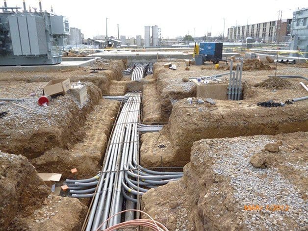
Underground PVC pipe - conduit

Underground PVC pipe – conduit (photo credit: s1inc.co)


NEC Article 352 applies to PVC conduit. PVC conduit is corrosion resistant and therefore used for many below-grade applications. It can be direct buried or encased in concrete.

Although PVC conduit can be used in exposed application as well, it is restricted to areas that are not subject to physical damage. There are other limitations to using PVC conduit that the design engineer and installer must consider, such as the fact that it will become brittle and difficult to work with in cold temperatures. This is of particular concern in northern climates where maintaining systems that have PVC conduit installed in exposed areas is a challenge.

At substation equipment, a transition from a non-metallic conduit to a metallic conduit is usually made. Type RMC, or rigid metal conduit (generally galvanized steel), is used for the above-grade conduit connection to substation equipment in the yard. NEC Article 344 applies to rigid metal conduit.

In northern climates, another consideration for conduit installations to equipment in the yard is frost. Frost depths there can reach up to four feet deep. Heaving related to the frost can cause conduit to push or pull equipment cabinets. The NEC provides articles on the use of these types of installations (Sections 300.7(B) and 250.98).

A few examples that may help minimize the upward movement of conduit into enclosures include; using flexible conduit or expansion fittings, and site grading practices or local foundation correction (i.e. deep sand layer).

The design engineer should consult with the requirements for frost depth in each state, as it can also impact the burial depth of the conduit.

While the substation design engineer will usually select the conduit type, routing, and sizing of the conduit used for the substation equipment in the yard, the conduit used within the electrical equipment enclosure will be selected and installed by the electrician or electrical equipment enclosure manufacturer.

The type of conduit generally used for this application is electrical metallic tubing (EMT).

EMT will generally be routed on the walls inside the electrical equipment enclosure. When installed with proper fittings, it can be used as the equipment grounding conductor. However, running a separate equipment grounding conductor with the phase conductor(s) to lights or receptacles within the electrical equipment enclosure is preferred. See Article 358 for requirements pertaining to EMT conduit.

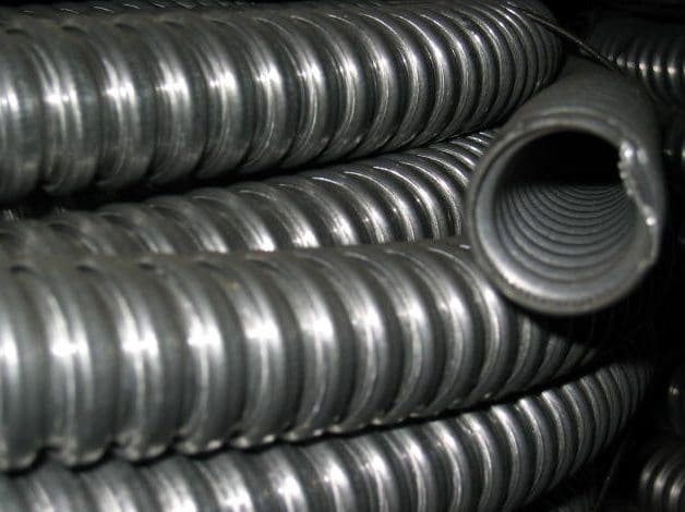
Flexible steel conduits for electrical cables

Flexible steel conduits for electrical cables (photo credit: arenametal.com)


The typical design of a conduit system will include conduit burial depth, bending radius, calculations on conduit fill, and determination of cable ampacity de-rating. Each of these criteria is covered in the NEC. Along with these design considerations, installation considerations are also addressed by the NEC, such as how the conduit is to be supported and secured.

Burial depth for conduit containing low-voltage wiring is covered under NEC Section 300.5 “Underground Installations”.

This NEC section covers the burial depth for cable and conduit. While the NEC permits PVC conduit to be installed at a depth of 18”, consideration must also be given to local codes, frost depth, cable ampacity, and the conduit bending radius. The bending radius for each trade size of conduit is covered in Table 2 of Chapter 9 in the NEC.

Circuits exceeding 600V have additional depth requirements and are covered under Section 300.50 of the NEC. PVC conduits used for circuits from 22kV to 40kV are required to be at least 24” deep. The increased depth must also be taken into account when calculating ampacity of the cables within the conduit, see NEC Section 310.60(C)(2).

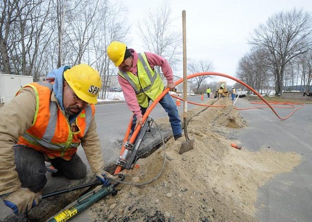
Orange conduit for fiber optic cables buried under Industrial Blvd in Montague (photo credit: recorder.com)

Orange conduit for fiber optic cables buried under Industrial Blvd in Montague (photo credit: recorder.com)


Maximum fill percentages for conduit are covered in Table 1 of Chapter 9 in the NEC.

For most substation applications, there will be more than two conductors in a conduit, so the maximum fill percentage will be 40%.

It is important to consider the length of the conduit run and the number of bends in the conduit runs when determining the amount of fill that is acceptable. The maximum fill percentage will not guarantee an easy installation. Other considerations associated with the fill of the conduit and the ease of installation is the jamming ratio. While the NEC does not govern this, it does contain an informational note about its occurrence.

There are many different requirements for ampacity de-rating of cables, but specific to conduit is NEC Section 310.15(B)(3)(a), which addresses the number of current carrying conductors in a raceway.

Ampacity for cables can be required to be reduced to 35% of the original value. This section has several exceptions that should be examined for each application to reduce oversizing cable.

As mentioned above, there can be challenges when applying the NEC to larger underground medium voltage circuits. In order to meet the fill requirements of the NEC, PVC conduit sizes larger than 6” are often required for the cable used.

Many manufacturers produce 8” PVC electrical conduit, but the NEC specifically limits the size of conduit used for each type.

The maximum size PVC conduit allowed by NEC is 6”. While manufacturers do produce 8” conduit, it is not acceptable to use it in conjunction with the NEC, and it will not usually be UL listed. It is up to the engineer to work with the authority having jurisdiction to determine if the use of 8” conduit is acceptable.

The NESC also contains a section on underground conduit systems in respect to the installation and maintenance of underground electric supply and communication lines that should be considered.

Reference: Applying the National Electrical Code to Substations – Jeff Heinemann, Mark Scheid

Satellite communication for remote control and monitoring of substations

$
0
0
Satellite communication as an innovative solution for remote control and monitoring of substations

Satellite communication as an innovative solution for remote control and monitoring of substations (on photo: Pole mounted iDirect X1 outdoor remote & power supply using a .75M antenna via blog.idirect.net)

Application for substation automation

Substation Automation is a supervisory management and control system that lies in between transmission and distribution systems.

The interests on substation automation have been increasing rapidly due to its numerous benefits to utilities. It has advanced further than a traditional Supervisory Control and Data Acquisition (SCADA) system providing additional capability and information that can be used to further improve operations, maintenance and efficiencies in substations.

The most significant elements of a substation automation system include relays and/or Intelligent Electronic Devices (IEDs) that perform various control, monitoring and protection related operations.

The desire and the need of merging the communication capabilities of all relays and IEDs in a substation has thus been clearly recognized, which is capable of providing not only data gathering and setting capability but also remote control.

Alstom Grid’s P60 Agile new range of intelligent electronic devices (IEDs) one-box solution” for the protection, control, recording and measurement of electrical power systems

Alstom Grid’s P60 Agile new range of intelligent electronic devices (IEDs) one-box solution” for the protection, control, recording and measurement of electrical power systems


Furthermore, multiple IEDs can share data or control commands at higher speeds to perform new distributed protection, and control functions.

Interoperability needs to be achieved in a substation between protective relays from different manufacturers so that substation level interlocking, protection and control functions can be realized improving the efficiency of microprocessor based relay applications.


Satellite communication

Recent developments in communication technologies have enabled reliable remote control systems which have the capability of monitoring the real time operating conditions and performance of electric systems.

These communication technologies can be classified into four classes:

  1. Power line communication,
  2. Satellite communication (subject of this article)
  3. Wireless communication and
  4. Optical fiber communication.

Each communication technology has its own advantages and disadvantages that must be evaluated to determine the best communication infrastructure for substation automation. In this article, a review of satellite communication technology is presented with the special emphasis on their application for substation automation.

Satellite communication can offer pretty innovative solutions for remote control and monitoring of substations.

It provides an extensive geographic coverage, and thus, can be a good alternative communication infrastructure for electric system automation in order to reach remote substations where other communication infrastructures such as telephone or cellular networks might not exist.

In practical applications, Very Small Aperture Terminal (VSAT) satellite services are already available that are especially tailored for remote substation monitoring applications.

Furthermore, with the latest developments in electric system automation, satellite communication is not only used for remote control and monitoring of substations, but also used for Global Positioning System (GPS) based time synchronization, which provides microsecond accuracy in time synchronization.

In addition, satellites can be used as a backup for the existing substations communication networks. In case of congestion or link failures in communication, critical data traffic can be routed through satellites.

In this article, both advantages and disadvantages of satellite communication technologies have been reviewed with respect to substation automation.


110/10 kV power substation in Russia, Northwestern

110/10 kV power substation in Russia, Northwestern (photo credit: ctsspb.com)

Two advantages

Following are the advantages of using satellite communication for remote monitoring:

1. Geographic coverage

Satellite communications have unique advantages over conventional long distance transmissions. This communication trend is capable of spanning long distance irrespective of the physical condition.

Thus providing a cost–effective solution for the areas where communication infrastructure might not exist due to environmental issues.

2. Higher Bandwidth

Satellite communication has very large bandwidth capacity as it is widely used for the broadcasting of video streaming. Thus this higher bandwidth can be utilized for the transmission of mission critical data and messages within substations.


Two disadvantages

Followings are the disadvantages of using satellite communication as a communication technology:

1. Long delay

As for as the transmission characteristics for satellite communication are concerned, round–trip delay is the growing concern which is comparatively higher than the wired network.

As substation messages are mission critical so in order to ensure efficient and reliable transmission of these message from one substation to other substation this round trip delay need to be minimized.

2. Satellite channel characteristics

Performance of satellite channels is greatly affected by the change in operating climate due to weather or by the effect of fading thereby degrading the efficiency of the whole satellite communication system.

Reference: A Survey of Communication Network Paradigms for Substation Automation – Mahmood Qureshi, Ali Raza, Dileep Kumar, Sang–Sig Kim, Un–Sig Song, Min–Woo Park, and Hyuk–Soo Jang, Hyo–Sik Yang and Byung–Seok Park

Site selection considerations for the future power substation

$
0
0
Site selection considerations for the future substation

Site selection considerations for the future substation (on photo: Richmond Substation by Tyler Wilson via Flickr)

Final location of the facility

At this stage, a footprint of the future power substation should be developed, including the layout of the major equipment. A decision on the final location of the facility can now be made and various options can be evaluated.

Final grades, roadways, storm water retention, and environmental issues are addressed at this stage, and required permits are identified and obtained.

Community and political acceptance must be achieved and details of station design are negotiated in order to achieve consensus.

Depending on local zoning ordinances, it may be prudent to make settlement on the property contingent upon successfully obtaining zoning approval since the site is of little value to the utility without such approval. It is not unusual for engineering, real estate, public affairs, legal, planning, operations, and customer service personnel along with various levels of management to be involved in the decisions during this phase.

The first round of permit applications can now begin! Although the zoning application is usually a local government issue, permits for grading, storm-water management, roadway access, and other environmental or safety concerns are typically handled at the state or provincial level and may be federal issues in the case of wetlands or other sensitive areas.

Other federal permits may also be necessary, such as those for aircraft warning lights for any tall towers or masts in the station.

Permit applications are subject to unlimited bureaucratic manipulation and typically require multiple submissions and could take many months to reach conclusion. Depending on the local ordinances, zoning approval may be automatic or may require hearings that could stretch across many months.

Zoning applications with significant opposition could take years to resolve.

Site evaluation criteria

As a rule of thumb, the following site evaluation criteria could be used:

  1. Economical evaluation
  2. Technical evaluation
  3. Community acceptance

Economical evaluation should address the level of affordability, return on investment, initial capital cost, and life cycle cost.

Technical aspects that can influence the site selection process could include the following:

  • Land: choose areas that minimize the need for earth movement and soil disposal.
  • Water: avoid interference with the natural drainage network.
  • Vegetation: choose low productivity farming areas or uncultivated land.
  • Protected areas: avoid any areas or spots listed as protected areas.
  • Community planning: avoid urban areas, development land, or land held in reserve for future development.
  • Community involvement: engage community in the approval process.
  • Topography: flat but not prone to flood or water stagnation.
  • Soil: suitable for construction of roads and foundations; low soil resistivity is desirable.
  • Access: easy access to and from the site for transportation of large equipment, operators, and maintenance teams.
  • Line entries: establishment of line corridors (alternatives: multi-circuit pylons, UG lines).
  • Pollution: risk of equipment failure and maintenance costs increase with pollution level.

To address community acceptance issues it is recommended to:

  • Adopt a low profile layout with rigid buses supported on insulators over solid shape steel structures.
  • Locate substations in visually screened areas (hills, forest), other buildings, and trees.
  • Use gas insulated switchgear (GIS).
  • Use colors, lighting.
  • Use underground egresses as opposed to overhead.

Other elements that may influence community acceptance are noise and oil leakages or spills.

To mitigate noise that may be emitted by station equipment, attention should be paid at station orientation with respect to the location of noise sensitive properties and use of mitigation measures such as noise barriers, sound enclosures, landscaping, and active noise cancellation.

Reference: Jim Burke (Baltimore Gas & Electric Company); Anne-Marie Sahazizian (Hydro One Networks, Inc.)


Main and Transfer (Inspection) Bus Arrangement commonly used in AIS

$
0
0
Main and Transfer (Inspection) Bus Arrangement commonly used in AIS

Main and Transfer (Inspection) Bus Arrangement commonly used in AIS (on photo: Air insulated substation in Kuwait; credit: ABB)

For low reliability requirement situations

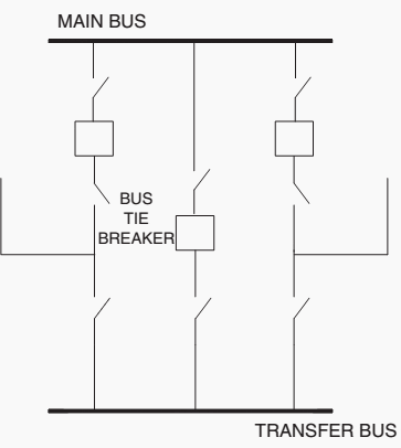
The main and transfer bus configuration connects all circuits between the main bus and a transfer bus (sometimes referred to as an inspection bus). Some arrangements include a bus tie breaker and others simply utilize switches for the tie between the two buses.

This configuration is similar to the single bus arrangement; in that during normal operations, all circuits are connected to the main bus.

So the operating reliability is low; a main bus fault will de-energize all circuits.

Main and transfer bus arrangement.

Figure 1 – Main and transfer bus arrangement.


However, the transfer bus is used to improve the maintenance process by moving the line of the circuit breaker to be maintained to the transfer bus. Some systems are operated with the transfer bus normally de-energized. When a circuit breaker needs to be maintained, the transfer bus is energized through the tie breaker.

Then the switch, nearest the transfer bus, on the circuit to be maintained is closed and its breaker and associated isolation switches are opened. Thus transferring the line of the circuit breaker to be maintained to the bus tie breaker and avoiding interruption to the circuit load.

Without a bus tie breaker and only bus tie switches, there are two options:

1st option

The first option is by transferring the circuit to be maintained to one of the remaining circuits by closing that circuit’s switch (nearest to the transfer bus) and carrying both circuit loads on the one breaker.

This arrangement most likely will require special relay settings for the circuit breaker to carry the transferred load.

2nd option

The second option is by transferring the circuit to be maintained directly to the main bus with no relay protection from the substation. Obviously in the latter arrangement, relay protection (recloser or fuse) immediately outside the substation should be considered to minimizefaults on the maintained line circuit from causing extensive station outages.

The cost of the main and transfer bus arrangement is more than the single bus arrangement because of the added transfer bus and switching devices. In addition, if a low-profile configuration is used, land requirements are substantially more.

Connections of lines to the station should not be very complicated. If a bus tie breaker is not installed, consideration as to normal line loading is important for transfers during maintenance. If lines are normally operated at or close to their capability, loads will need to be transferred or temporary generators provided similar to the single bus arrangement maintenance scenario.

The main and transfer bus arrangement is an initial stage configuration, since a single main bus failure can cause an outage of the entire station.

As load levels at the station rise, consideration of a main bus tie breaker should be made to minimize the amount of load dropped for a single contingency.

Another operational capability of this configuration is that the main bus can be taken out-of-service without an outage to the circuits by supplying from the transfer bus, but obviously, relay protection (recloser or fuse) immediately outside the substation should be considered to minimize faults on any of the line circuit from causing station outages.

Application of this type of configuration should be limited to low reliability requirement situations.

Switching operation

  1. First close the isolators at both side of the bus coupler breaker.
  2. Then close the bypass isolator of the feeder which is to be transferred to transfer bus.
  3. Now energized the transfer bus by dosing the bus coupler circuit breaker from remote.
  4. After bus coupler breaker is closed, now the power from main bus flows to the feeder line through its main breaker as well as bus coupler breaker viatransfer bus.
  5. Now if main breaker of the feeder is switched off, total power flow will instantaneously shift to the bus coupler breaker and hence this breaker will serve the purpose of protection for the feeder.
  6. At last the operating personnel open the isolators at both sides of the main circuit breaker to make it isolated from rest of the live system.
References:
  • Air-Insulated Substations — Bus Switching Configurations / Michael J. Bio
  • Substation layout and accessories and busbar arrangement – Amit Kumar, Nejamul Hoque and Hemendra Kumar Rajput

Ring Main Unit (RMU) as an important part of secondary distribution substations

$
0
0
Ring Main Unit as an important part of Secondary Distribution Substations

Ring Main Unit as an important part of Secondary Distribution Substations (on photo: ABB’a 24kV RMU type ‘SafeRing’)

RMU

A Ring Main Unit (RMU) is a totally sealed, gas-insulated compact switchgear unit. The primary switching devices can be either switch disconnectors or fused switch disconnectors or circuit breakers.

Different combinations of these primary switching devices within the unit are commonly used.

An example of distribution network with Ring Main Units

An example of distribution network with Ring Main Units (combinations of RMU units by Schneider Electric)


In case a circuit breaker is the switching device, it is also equipped with protective relaying, either with a very basic self-powered type or a more advanced one with communication capabilities.

The rated voltage and current ranges for RMUs typically reach up to 24 kV and 630 A respectively. With many of the manufacturers of RMUs, the basic construction of the unit remains the same for the whole of the voltage range.

The increase in rated voltage is handled by an increase in the insulating gas pressure.

Single-line representation of a typical RMU configuration

Figure 1 – Single-line representation of a typical RMU configuration


The figure above shows a typical RMU configuration where load disconnectors are the switching devices for the incoming cable feeders and circuit breaker works as the switching device for distribution transformer feeder.


Three-position design // Closing, Opening and Earthing

All of the switching devices are of three-position design, having the possibility to close or open or earth the feeder in question.

All switches can be operated with the included operating handle

All switches can be operated with the included operating handle


Closing

Closing the moving contact assembly is manipulated by means of a fast-acting operating mechanism. Outside these manipulations, no energy is stored. For the circuit breaker and the fuse-switch combination, the opening mechanism is charged in the same movement as the closing of the contacts.

Turn the operating handle clockwise to charge the close/open spring. Then push the green button. (A)

Turn the operating handle clockwise to charge the close/open spring. Then push the green button. (A)


Opening

Opening of the switch is carried out using the same fast-acting mechanism, manipulated in the opposite direction. For the circuit breaker and fuse-switch combination, opening is actuated by:

  • A pushbutton
  • A fault.
Push the red button (B) to open fuse switch disconnector

Push the red button (B) to open fuse switch disconnector


Earthing

A specific operating shaft closes and opens the earthing contacts. The hole providing access to the shaft is blocked by a cover which can be opened if the switch or circuit breaker is open, and remains locked when it is closed.

Close earthing switch by turning operating handle clockwise

Close earthing switch by turning operating handle clockwise


The figure below shows typical outlook of a three-feeder RMU. In the figure, the combination consists of load disconnectors for the incoming two feeders and a fused load disconnector for the distribution transformer feeder. The incoming and outgoing medium-voltage cables are attached using elbow-type plug-in cable ends.

Outlook of a typical three-feeder 24 kV RMU unit

Figure 2 – Outlook of a typical three-feeder 24 kV RMU unit (ABB’s SafeRing RMU)


Whereas the RMU type of units represents the very compact gas-insulated design for a dedicated purpose, the secondary medium-voltage switchgears represent an air-insulated, quite freely extendable and configurable solution.

References:

  • Distribution Automation Handbook // Elements of power distribution systems – ABB
  • RM6 Ring main Unit catalogue – Schneider Electric
  • MV RMU SafeRing catalogue – ABB

How can I select the right capacitors for my specific application needs?

$
0
0
How can I select the right capacitors for my specific application needs?

How can I select the right capacitors for my specific application needs? (photo credit: mediarede.com)

Power factor correction

Once you’ve decided that your facility can benefit from power factor correction, you’ll need to choose the optimum type, size, and number of capacitors for your plant.

There are two basic types of capacitor installations: individual capacitors on linear or sinusoidal loads, and banks of fixed or automatically switched capacitors at the feeder or substation.

Individual vs. banked installations

7 advantages of individual capacitors at the load:

  1. Complete control // Capacitors cannot cause problems on the line during light load conditions
  2. No need for separate switching // Motor always operates with capacitor
  3. Improved motor performance due to more efficient power use and reduced voltage drops
  4. Motors and capacitors can be easily relocated together
  5. Easier to select the right capacitor for the load
  6. Reduced line losses
  7. Increased system capacity

3 advantages of bank installations at the feeder or substation:

  1. Lower cost per kVAR
  2. Total plant power factor improved – reduces or eliminates all forms of kVAR charges
  3. Automatic switching ensures exact amount of power factor correction, eliminates over-capacitance and resulting overvoltages

Table 1 // Summary of Advantages/Disadvantages of Individual, Fixed Banks, Automatic Banks, Combination

MethodAdvantagesDisadvantages
Individual capacitorsMost technically efficient, most flexibleHigher installation and maintenance cost
Fixed bankMost economical, fewer installationsLess flexible, requires switches and/or circuit breakers
Automatic bankBest for variable loads, prevents overvoltages, low installation costHigher equipment cost
CombinationMost practical for larger numbers of motorsLeast flexible

Consider the 5 particular needs of your plant

When deciding which type of capacitor installation best meets your needs, you’ll have to weigh the advantages and disadvantages of each and consider several plant variables, including load type, load size, load constancy, load capacity, motor starting methods, and manner of utility billing.

1. Load type //

If your plant has many large motors, 50 hp and above, it is usually economical to install one capacitor per motor and switch the capacitor and motor together. If your plant consists of many small motors, 1/2 to 25 hp, you can group the motors and install one capacitor at a central point in the distribution system.

Often, the best solution for plants with large and small motors is to use both types of capacitor installations .

2. Load size //

Facilities with large loads benefit from a combination of individual load, group load, and banks of fixed and automatically-switched capacitor units. A small facility, on the other hand, may require only one capacitor at the control board.

Sometimes, only an isolated trouble spot requires power factor correction. This may be the case if your plant has welding machines, induction heaters, or DC drives. If a particular feeder serving a low power factor load is corrected, it may raise overall plant power factor enough that additional capacitors are unnecessary.

3. Load constancy //

If your facility operates around the clock and has a constant load demand, fixed capacitors offer the greatest economy. If load is determined by eight-hour shifts five days a week, you’ll want more switched units to decrease capacitance during times of reduced load.

4. Load capacity //

If your feeders or transformers are overloaded, or if you wish to add additional load to already loaded lines, correction must be applied at the load. If your facility has surplus amperage, you can install capacitor banks at main feeders.

If load varies a great deal, automatic switching is probably the answer.

5. Utility billing //

The severity of the local electric utility tariff for power factor will affect your payback and ROI (return of investment). In many areas, an optimally designed power factor correction system will pay for itself in less than two years.

Reference: Power factor correction – A guide for the plant engineer – EATON (Download paper)

6 Transformer Types You Can See In Commercial Installations

$
0
0
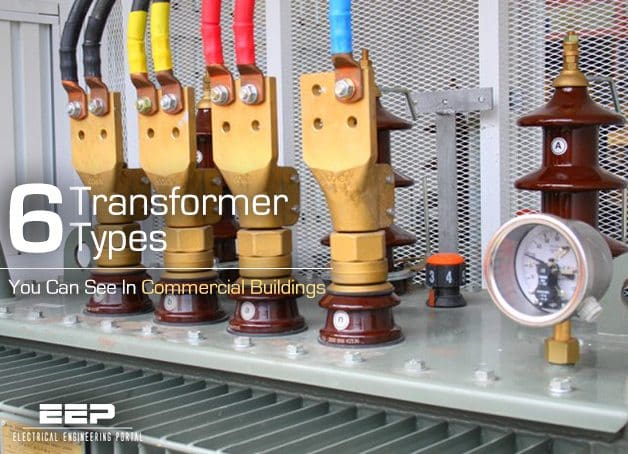
6 Transformer Types You Can See In Commercial Buildings

6 Transformer Types You Can See In Commercial Buildings (photo credit: iml.bg)

Transformer Types and their Characteristics

Transformers in commercial installations are normally used to change a voltage level from a utility distribution voltage to a voltage that is usable within the building, and are also used to reduce building distribution voltage to a level that can be utilized by specific equipment. Applicable standards are the ANSI C57 Series and NEMA TR and ST Series.

The following six types of transformers are normally used in commercial buildings:

  1. Substation
  2. Primary-unit substation
  3. Secondary-unit substation (power center)
  4. Network
  5. Pad-mounted
  6. Indoor distribution

Many other types of transformers are manufactured for special applications, such as welding, constant voltage supply, and high-impedance requirements. Discussion of the special transformers and their uses is beyond the scope of this recommended practice.


1. Substation Transformers

Used with outdoor substations, they are rated 750-5000 kVA for single-phase units and 750-25 000 kVA for three-phase units.

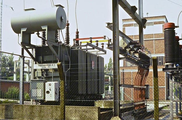
High voltage transformer 40MVA

High voltage transformer 40MVA (Steps down 150kv to 10kV in a substation in Belgium. Photo taken 1983.)


The primary voltage range is 2400 V and up. Taps are usually manually operated while de-energized; but automatic load tap changing may be obtained. The secondary voltage range is 480-13 800 V. Primaries are usually delta connected, and secondaries are usually wye connected because of the ease of grounding the secondary neutral.

The insulation and cooling medium is usually liquid. High-voltage connections are on cover-mounted bushings. Low-voltage connections may be cover-mounted bushings or an air terminal chamber.

Go back to Index ↑


2. Primary-Unit Substation Transformers

Used with their secondaries connected to medium-voltage switchgear, they are rated 1000-10 000 kVA and are three-phase units. The primary voltage range is 6900-138 000 V. The secondary voltage range is 2400-34 500 V.

Primary-Unit Substation Transformer

Primary-Unit Substation Transformer (photo credit: actom.co.za)


Taps are usually manually changed while de- energized; but automatic load tap changing may be obtained. Primaries are usually delta connected. The type may be oil, less-flammable liquid, air, dry, cast-coil, or gas. The high-voltage connections may be cover bushings, an air terminal chamber, or throat. The low-voltage connection is a throat.

Go back to Index ↑


3. Secondary-Unit Substation Transformers

Used with their secondaries connected to low-voltage switchgear or switchboards, they are rated 112.5-2500 kVA and are three-phase units. The primary voltage range is 2400-34 500 V. The taps are manually changed while de-energized. The secondary voltage range is 120-480 V.

Trihal - Dry-type transformer 1600 kVA 10/0,42kV connected to busbar system Canalis KTA 2500A (Schneider Electric)

Trihal – Dry-type transformer 1600 kVA 10/0,42kV connected to busbar system Canalis KTA 2500A (Schneider Electric)


The primaries are usually delta-connected, and secondaries are usually wye connected. The type may be oil, less-flammable liquid, air, dry, cast-coil, or gas. The high-voltage connections may be cover bushings, an air terminal chamber, or throat. The low-voltage connection is a throat but it may also be by bus duct.

Go back to Index ↑


4. Network Transformers

Used with secondary-network systems, they are rated 300-2500 kVA. The primary voltage range is 4160-34 500 V. The taps are manually operated while de-energized. The secondary voltages are 208Y/120 V and 480Y/277 V.

Network transformer - Subway type

Network transformer – Subway type (photo credit: pioneertransformers.com)


The type may be oil, less-flammable liquid, air, dry, cast-coil, or gas. The primary is delta connected, and the secondary is wye-connected. The high-voltage connection is generally a network switch (on-off-ground) or an interrupter-type switch with or without a ground position. The secondary connection is generally an appropriate network protector, or a low-voltage power air circuit breaker designed to provide the functional equivalent of a network protector.

A subway-type unit is suitable for frequent or continuous operation while submerged in water; a vault-type unit is suitable for occasional submerged operation.

Go back to Index ↑


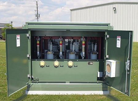
5. Pad-Mounted Transformers

Used outside buildings where conventional unit substations might not be appropriate, and are either single-phase or three-phase units. Because they are of tamper-resistant construction, they do not require fencing.

Pad-mount outdoor transformer

Pad-mount outdoor transformer


Primary and secondary connections are made in compartments that are adjacent to each other but separated by barriers from the transformer and each other. Access is through padlocked hinged doors designed so that unauthorized personnel cannot enter either compartment.

Where ventilating openings are provided, tamper-resistant grills are used. Gauges and accessories are in the low- voltage compartment.

  • These units are rated 75-2500 kVA.
  • The primary voltage range is 2400-34 500 V.
  • Taps are manually changed while de-energized.
  • The secondary voltage range is 120-480 V.

Primaries are almost always delta connected or special construction wye connected, and secondaries are usually wye connected. A delta-connected tertiary is not acceptable with a three-legged core unless an upstream device opens all three phases for a single-phase fault.

The type may be oil, less-flammable liquid, air, dry, cast-coil, or gas. The high-voltage connection is in an air terminal chamber that may contain just pressure- or disconnecting-type connectors or may have a disconnecting device, either fused or unfused. The connections may be for either single or loop feed. The low-voltage connection is usually by cable at the bottom; but it may also be by bus duct.

Cant see this video? Click here to watch it on Youtube.

The dry-type, pad-mounted transformer does not have the inherent fire hazards of the oil filled, pad-mounted transformer and frequently the dry-type, pad-mounted transformer is mounted on the roofs of buildings so that it will be as near to the load center as possible.

ANSI C57.12.22-1989 [5] applies to oil immersed units with primary voltages of 16 340 V and below.

Go back to Index ↑


6. Indoor Distribution Transformers

Used with panelboards and separately mounted, they are rated 1-333 kVA for single-phase units and 3-500 kVA for three-phase units. Both primaries and secondaries are 600 V and below (the most common ratio is 480-208Y/120V).

Indoor substation transformer

Indoor substation transformer


The cooling medium is air (ventilated or nonventilated). Smaller units have been furnished in encapsulated form. High- and low-voltage connections are pressure-type connections for cables. Impedances of distribution transformers are usually lower than those of substation or secondary-unit substation transformers.

Indoor and outdoor distribution transformers are also available at primary voltages of up to 34 500 V and 150 kV basic impulse insulation level (BIL).

The majority of transformers for distributing power at 480 V in a commercial building are usually referred to as “general-purpose transformers” and secondaries are typically rated at 208Y/120 V. These transformers are mostly of the dry-type, and some of the smaller sized ones are encapsulated. General-purpose transformers are used for serving 120 V lighting, appliances, and receptacles.

Go back to Index ↑


Other Transformer Types //

Virtually all power transformers used in commercial buildings are of the two-winding type, which may be referred to as isolating or insulating transformers, and are distinct from the one-winding type known as the autotransformer. The two-winding-type transformer provides a positive isolation between the primary and secondary circuits; which is desirable for safety, circuit isolation, reduction of fault levels, coordination, and reduction of electrical interference.

There are also a number of “specialty transformers” used for applications, such as x-ray machines, laboratories, electronic equipment, and special machinery applications.

Specialty transformers used in applications where the least amount of leakage current could cause an arc and ignite the atmosphere (such as in an oxygenated environment) or cause personal injury (such as in open heart surgery) will require an ungrounded secondary.

Direct-Current Electric Arc Furnace (DC EAF) Transformer

Figure 2 – Direct-Current Electric Arc Furnace (DC EAF) Transformer


In the most sensitive applications, the leakage current may be monitored and is controlled by introducing a grounded shield between the primary and secondary coils. Such a shield also reduces electromagnetic interference (EMI), which may be present in the primary.

Reference // IEEE Recommended Practice for Electric Power Systems in Commercial Buildings

Important Primary Distribution (Radial and Loop) System Considerations

$
0
0
Important Primary Distribution (Radial and Loop) System Considerations

Important Primary Distribution (Radial and Loop) System Considerations (photo credit: archer-elgin.com)

Primary (distribution) feeders //

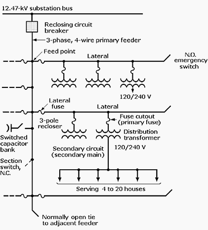
The primary distribution system is that part of the electric distribution system between the distribution substation and distribution transformers. It is made up of circuits called primary feeders or distribution feeders. These feeders include the primary feeder main or main feeder, usually a three-phase, four-wire circuit, and branches or laterals, which can be either three-phase or single-phase circuits.

These are tapped from the primary feeder main, as shown in the simplified distribution feeder diagram of Figure 1. A typical power distribution feeder provides power for both primary and secondary circuits.

Simplified diagram of a power distribution feeder

Figure 1 – Simplified diagram of a power distribution feeder


In primary system circuits, three-phase, four-wire, multigrounded common-neutral systems, such as 12.47Y/7.2 kV, 24.9Y/14.4 kV, and 34.5Y/19.92 kV, are used almost exclusively. The fourth wire of these Y-connected systems is the neutral, grounded at many locations for both primary and secondary circuits.

Single-phase loads are served by distribution transformers with primary windings that are connected between a phase conductor and the neutral.

Three-phase loads can be supplied by three-phase distribution transformers or by single-phase transformers connected to form a three-phase bank. Primary systems typically operate in the 15kV range, but higher voltages are gaining acceptance.

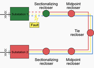
The primary feeder main is usually sectionalized by reclosing devices positioned at various locations along the feeder. This arrangement minimizes the extent of primary circuitry that is taken out of service if a fault occurs. Thus the reclosing of these devices confines the outage to the smallest number of customers possible. This can be achieved by coordinating all the fuses and reclosers on the primary feeder main.

In above block diagram Figure 1, distribution substation voltage is 12.47 kV line-to-line and 7.2 kV line-to-neutral (this is conventionally written as 12,470Y/7200 V). However, the trend is toward higher primary four-wire distribution voltages in the 25kV to 35kV range. Single-phase feeders such as those serving residential areas are connected line-to-neutral on the four-wire systems.

The use of underground primary feeders that are radial three-conductor cables is increasing. They are serving urban areas where load demand is heavy, particularly during the hot summer months, and newer suburban residential developments. Both cost factors and the importance of reliability to the customers being served influence the design of primary systems.


Radial and Loop Distribution Systems //

Comparison

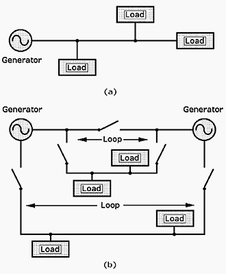
The simplest and least expensive (as well as least reliable) configuration is the radial distribution system shown in Figure 2a, because it depends on a single power source.

Simplified diagrams of the basic electrical distribution systems: (a) radial and (b) loop

Simplified diagrams of the basic electrical distribution systems: (a) radial and (b) loop


Despite their lower reliability, radial systems remain the most economical and widely used distribution systems for serving homes because an electrical power outage there is less likely to have serious economic or public safety consequences.

As a hedge against outages, most utilities plan their distribution systems so that they will have backup if those events occur. The goal of all electrical distribution systems is the economic and safe delivery of adequate electric power to serve the electrical loads.

The reliability of the primary feeder can be improved with the installation of a loop distribution system, as shown in Figure 2b.

In loop systems the feeder, which originates at one bulk power source, “loops” through the service area and several substations before terminating at the original substation or another bulk source. The strategic placement of switches at the substations permits the electric utility to supply customers in either direction.

If one power source fails, switches are opened or closed to bring an alternative power source online.

Loop systems provide better service continuity than radial systems, with only short service interruptions during switching. However, they are more expensive than radial systems because of the additional switching equipment requirements. As a result, loop systems are usually built to serve commercial and light industrial buildings and shopping malls, where power outages are more likely to endanger human lives or result in property losses.
Reliability and service quality can be significantly improved at even higher cost with a multiple parallel circuit pattern. In these systems, two or more circuits are tapped at each substation. The circuits can be radial or they can terminate in a second bulk power source. These interconnections permit each circuit to be supplied by many different substations.

Reference: Handbook of electrical design details // Second edition – Neil Sclater; John E. Traister (Purchase ebook)

Configurations and Characteristics Of Distribution Substations

$
0
0
Configurations and Characteristics Of Distribution Substations

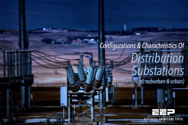
Configurations and Characteristics Of Distribution Substations (on photo: Distribution Substation on the Prairie by hunter20ga via Flickr )

Small, medium, and large substations

Distribution substations come in many sizes and configurations. A small rural substation may have a nominal rating of 5 MVA while an urban station may be over 200 MVA.

Figures 1 through 3 show examples of small, medium, and large substations. As much as possible, many utilities have standardized substation layouts, transformer sizes, relaying systems, and automation and SCADA (supervisory control and data acquisition) facilities. Most distribution substation bus configurations are simple with limited redundancy.

Example rural distribution substation

Figure 1 – Example rural distribution substation


Transformers smaller than 10 MVA are normally protected with fuses, but fuses are also used for transformers to 20 or 30 MVA. Fuses are inexpensive and simple; they don’t need control power and take up little space. Fuses are not particularly sensitive, especially for evolving internal faults.

Larger transformers normally have relay protection that operates a circuit switcher or a circuit breaker. Relays often include differential protection, sudden-pressure relays, and overcurrent relays.

Both the differential protection and the sudden-pressure relays are sensitive enough to detect internal failures and clear the circuit to limit additional damage to the transformer. Occasionally, relays operate a high-side grounding switch instead of an interrupter. When the grounding switch engages, it creates a bolted fault that is cleared by an upstream device or devices.

The feeder interrupting devices are normally relayed circuit breakers, either free-standing units or metal-enclosed switchgear. Many utilities also use reclosers instead of breakers, especially at smaller substations.

Station transformers are normally protected by differential relays which trip if the current into the transformer is not very close to the current out of the transformer. Relaying may also include pressure sensors. The high-side protective device is often a circuit switcher but may also be fuses or a circuit breaker.

Example suburban distribution substation

Figure 2 – Example suburban distribution substation


Two-bank stations are very common (Figure 2); these are the standard design for many utilities. Normally, utilities size the transformers so that if either transformer fails, the remaining unit can carry the entire substation’s load. Utility practices vary on how much safety margin is built into this calculation, and load growth can eat into the redundancy.

Most utilities normally use a split bus: a bus tie between the two buses is normally left open in distribution substations. The advantages of a split bus are:

  • Lower fault current – This is the main reason that bus ties are open. For a two-bank station with equal transformers, opening the bus tie cuts fault current in half.
  • Circulating current – With a split bus, current cannot circulate through both transformers.
  • Bus regulation – Bus voltage regulation is also simpler with a split bus. With the tie closed, control of paralleled tap changers is more difficult.

Having the bus tie closed has some advantages, and many utilities use closed ties under some circumstances. A closed bus tie is better for:

  • Secondary networks – When feeders from each bus supply either spot or grid secondary networks, closed bus ties help prevent circulating current through the secondary networks.
  • Unequal loading – A closed bus tie helps balance the loading on the transformers. If the set of feeders on one bus has significantly different loading patterns (either seasonal or daily), then a closed bus tie helps even out the loading (and aging) of the two transformers.
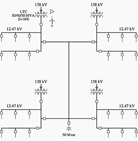
Example urban distribution substation

Figure 3 – Example urban distribution substation


Whether the bus tie is open or closed has little impact on reliability. In the uncommon event that one transformer fails, both designs allow the station to be reconfigured so that one transformer supplies both bus feeders.

The closed-tie scenario is somewhat better in that an automated system can reconfigure the ties without total loss of voltage to customers (customers do see a very large voltage sag). In general, both designs perform about the same for voltage sags.

Urban substations are more likely to have more complicated bus arrangements. These could include ring buses or breaker-and-a-half schemes.

Figure 3 shows an example of a large urban substation with feeders supplying secondary networks. If feeders are supplying secondary networks, it is not critical to maintain continuity to each feeder, but it is important to prevent loss of any one bus section or piece of equipment from shutting down the network (an N-1 design).


Electrical Distribution Substation Tour (VIDEO)

Cant see this video? Click here to watch it on Youtube.

Reference // Electric Power Distribution Equipment and Systems – T.A.Short (Purchase from Amazon)

Basic Stand-Alone Application of Reclosers

$
0
0
Basic Stand-Alone Application of Reclosers

Basic Stand-Alone Application of Reclosers (photo credit: Spanish via Flickr)

Overcurrent protection

Reclosers are self-contained fault interrupting and reclosing devices, specifically designed for overcurrent protection in secondary distribution systems.

Reclosers are situated in selected locations within the overhead distribution network. With the correct protection setting and MV fuse selection coordination, concerning the whole supply loop from the supplying primary distribution substation feeder to the fuse-protected distribution transformer, it is possible to achieve a discriminative fault isolation function.

Traditionally, the recloser units do not have any remote communication facilities. To enhance the system monitoring and restoration facilities, the reclosers can be equipped with remote communicating protection and control units.

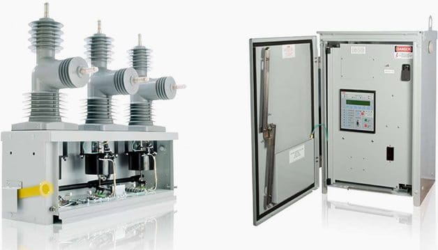
The recloser assembly consists of the fault-breaking primary unit, typically pole-mounted with brackets, and a control cabinet mounted near the ground level. Both three-phase and single-phase units are used, depending on the secondary distribution operation and protection philosophy. The current measuring is carried out with internally mounted bushing current transformers.

The switching device is typically either a vacuum-type or oil-type of a circuit breaker with nominal currents up to 1250A and a rated voltage up to 38kV. The breaking capacity of the circuit breaker can reach up to 16kA.

Figure 1 – Typical recloser’s breaking unit (vacuum type) on the left and control cabinet on the right

ABB's recloser type 'OVR-3' - A three phase 15-38 kV, 630-1250 A

Figure 1 – ABB’s recloser type ‘OVR-3′ – A three phase 15-38 kV, 630-1250 A, magnetic actuated, no oil or SF6, and no electronics on the HV side, PCD controller with power supply capable of 48-hour carryover

Automatic fault isolation functionality

Following principal system diagrams describe one basic “stand-alone” application of reclosers.

The below described automatic fault isolation functionality has been achieved with the correct coordination of protection and auto-reclosing scheme settings. Red color marks for a closed switch and green color marks for an open switch.

Furthermore, a solid line marks for an energized line and a dashed line marks for a de-energized line.

In the first diagram, the two feeders are supplied from two separate primary distribution substations with the tie recloser open.

System status just before fault appears in the marked location

Figure 2 – System status just before fault appears in the marked location


The second diagram shows a permanent fault situation on the first feeder. As a result of the fault, the feeder in the substation has made an unsuccessful autoreclosing attempt and has locked out with the breaker open.

System status after unsuccessful autoreclosing of the supplying feeder in substation 1

Figure 3 – System status after unsuccessful autoreclosing of the supplying feeder in substation 1


In the third diagram, the sectionalizing recloser has opened, isolating the faulty section of the feeder.

Sectionalizing recloser has opened, isolating the faulty section of the feeder

Figure 4 – Sectionalizing recloser has opened, isolating the faulty section of the feeder


In the fourth diagram, the tie recloser has closed energizing the healthy section of the looped feeder.

System status after tie recloser has closed

Figure 5 – System status after tie recloser has closed

Gridshield Recloser Overview (VIDEO)

Cant see this video? Click here to watch it on Youtube.

Reference // ABB’s Distribution Automation Handbook – Elements of power distribution systems


Substation DC Auxiliary Supply – Battery And Charger Applications

$
0
0
DC voltage 110 V or 220 V Power substation can have one or several DC systems. Factors affecting the number of systems are the need of more than one voltage level and the need of duplicating systems. Today, normal DC auxiliary supply systems in power substation are operating either on the 110 V or 220 […]

Substation AC Auxiliary Supply For Inessential Loads

$
0
0
Auxiliary power supply systems The purpose of auxiliary power supply systems is to cater for the necessary energy for the operation of primary and secondary devices at the substation. The auxiliary power systems are normally divided in two categories, namely the AC system and the DC system(s). The AC system normally operates with the country’s […]

Basics Of Distribution Substations For Electrical Engineers (Beginners)

$
0
0
Distribution substations purpose // Distribution substations serve a wide range of private and public customers in distributing electric power. They can be shareholder, cooperatively, privately, and government owned. All substations contain power transformers and the voltage-regulating apparatus required for converting the high incoming sub-transmission voltages to lower primary system voltages and maintaining them within specified […]

6 Voltages a Person Can Be Exposed To In a Substation

$
0
0
Dangerous voltages in substation // Figures 1 and 2 show the voltages a person can be exposed to in a substation. The following definitions describe the voltages // Ground potential rise (GPR) Mesh voltage Metal-to-metal touch voltage Step voltage Touch voltage Transfer red voltage 1. Ground potential rise (GPR) The maximum electrical potential that a […]

Balancing of single-phase loads to achieve energy efficiency

$
0
0
Single-phase loads distribution // All single-phase loads, especially those with non-linear characteristics, in an electrical installation with a three-phase supply should be evenly and reasonably distributed among the phases. Such provisions are required to be demonstrated in the design for all three-phase 4-wire circuits exceeding 100A with single-phase loads. The maximum unbalanced single-phase loads distribution, […]
Viewing all 279 articles
Browse latest View live