Steps to Ensure Effective Substation Grounding (photo by Peak Power Engineering, Inc.)
Continued from previous article: Steps to Ensure Effective Substation Grounding (1)
Ensuring Proper Grounding
In previous technical article (part 1) was explained first five steps that will ensure a reliable, safe and trouble-free substation grounding system. Here we will explain the last six steps:
- Size conductors for anticipated faults (previous part 1)
- Use the right connections (previous part 1)
- Ground rod selection (previous part 1)
- Soil preparation (previous part 1)
- Attention to step and touch potentials (previous part 1)
- Grounding using building foundations
- Grounding the substation fence
- Special attention to operating points
- Surge arrestors must be grounded properly
- Grounding of cable trays
- Temporary grounding of normally energized parts
6. Grounding Using Building Foundations

The concrete operation to Building control foundation
Concrete foundations below ground level provide an excellent means of obtaining a low-resistance ground electrode system. Since concrete has a resistivity of about 30 Ωm at 20 °C, a rod embedded within a concrete encasement gives a very low electrode resistance compared to most rods buried in the ground directly.
Since buildings are usually constructed using steel-reinforced concrete, it is possible to use the reinforcement rod as the conductor of the electrode by ensuring that an electrical connection can be established with the main rebar of each foundation.
The size of the rebar as well as the bonding between the bars of different concrete members must be done so as to ensure that ground fault currents can be handled without excessive heating.
The use of ‘Ufer’ grounds (named after the person who was instrumental in the development of this type of grounding practice) has significantly increased in recent years. Ufer grounds utilize the concrete foundation of a structure plus building steel as a grounding electrode.
Even if the anchor bolts are not directly connected to the reinforcing bars (rebar), their close proximity and the conductive nature of concrete will provide an electrical path.
There are a couple of issues to be considered while planning for grounding using the foundations as electrodes. A high fault current (lightning surge or heavy ground fault) can cause moisture in the concrete to evaporate suddenly to steam.
This steam, whose volume is about 1800 times of its original volume when existing as liquid, produces forces that may crack or otherwise damage the concrete. The other factor has to do with ground leakage currents. The presence of even a small amount of DC current will cause corrosion of the rebar. Because corroded steel swells to about twice its original volume, it can cause extremely large forces within the concrete.
Although AC leakage will not cause corrosion, the earth will rectify a small percentage of the AC to DC. In situations where the anchor bolts are not bonded to the rebar, concrete can disintegrate in the current path.
That external electrode must be sized and connected to protect the concrete’s integrity. Proper design of Ufer grounds provides for connections between all steel members in the foundation and one or more metallic paths to an external ground rod or main ground grid.
Excellent joining products are available in the market, which are especially designed for joining rebars throughout the construction. By proper joining of the rebars, exceptionally good performance can be achieved.
An extremely low resistance path to earth for lightning and earth fault currents is ensured as the mass of the building keeps the foundation in good contact with the soil.
7. Grounding the Substation Fence
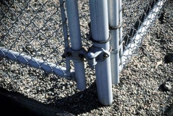
The second most common substation hazard is lack of grounding (photo from IAEI Magazine)
Metallic fences of substations should be considered just as other substation structures.
The reason for this is that the overhead HV lines entering or leaving a substation may snap and fall on the fence. Unless the fence is integrated with the rest of the substation grounding system, a dangerous situation may develop. Persons or livestock in contact with the fence may receive dangerous electric shocks.
Utilities vary in their fence-grounding specifications, with most specifying that each gate post and corner post, plus every second or third line post, be grounded. All gates should be bonded to the gate posts using flexible jumpers. All gate posts should be interconnected. In the gate swing area, an equipotential wire mesh safety mat can further reduce hazards from step and touch potentials when opening or closing the gate.
This can be accomplished by extending the mesh with a buried perimeter conductor that is about 1 m outside the fence and bonding the fence and the conductor together at close intervals (so that a person or grazing animal touching the fence will stand on the equipotential surface so created).
8. Special Attention to Operating Points
To protect the operator in case of a fault, it should be ensured that he is not subjected to high touch or step potentials when a fault happens in the equipment he is operating.
This calls for use of a safety mesh close to these operating points on which the operator will stand and operate the equipment.
1. A steel grate or plate on supporting insulators. This works only if the operator can be kept completely isolated on the grate. Therefore, insulators must be kept clean.
Any vegetation in the vicinity should be cut or eliminated completely (this approach is similar to the insulating rubber mats placed in front of most indoor electrical equipment). Safety is ensured by increasing the resistance of current path, so that the current flowing through the operator’s body into the ground does not exceed safe values.
2. A steel grate on the surface, permanently attached to the grounded structure. This arrangement has the operator standing directly on the grate.
3. Bare conductor buried (in a coil or zig-zag pattern) under the handle area and bonded to the grounded structure.
4. Prefabricated equipotential wire mesh safety mat buried under the handle area and bonded to the grounded structure. This is likely to be the least expensive choice.
In all but the first arrangement, both the switch operating handle and the personnel safety grate (or mat) should be exothermically weldedto structural steel, thus ensuring nearly zero voltage drop.
9. Surge Arrestors Must be Grounded Properly!
When there is a surge in the electrical system (by indirect lightning strikes or due to switching) surge arrestors placed near all critical equipment divert surge energy to ground and protect the equipment from being subjected to the surges.
Usually, surges involve a very fast rise time during which the current changes from zero to extremely high values of several kiloamperes. It is therefore necessary that the conducting path from the grounding terminal of the surge arrestor to the earth must have minimum impedance.
Even a small amount of self-inductance offered by a grounding conductor will mean very high impedance because of the steep wavefront of the surge and very high voltages from appearing in the grounding system (albeit briefly). To dissipate the surge current with minimum voltage drop, each surge arrestor ground lead should have a short direct path to earth and should be free of sharp bends (bends act like a coil and increase the inductance).
It must be ensured that multiple and secure paths to ground are available (this includes making effective connections).
Whenever there is any question about the adequacy of these paths, it is recommended to use a separate copper conductor between the arrestor and the ground terminal (or main grounding grid). Since steel structures (due to their multiple members) have lower impedance than a single copper conductor, the grounding conductors should preferably be interconnected to the structure near the arrestor.
10. Grounding of Cable Trays
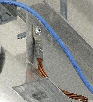
Overhead cable trays and ladder racks are jumpered and grounded with AWG #2 bare copper. These conductors, along with the cable bus that collects ground leads from individual cabinets, are connected to the nearest wall-mounted collector bar.
The NEC vide Art. 318 specifies the requirements for cable trays and their use in reducing the induced voltages during a ground fault. All metallic tray sections must be bonded together with proper conducting interconnections. The mechanical splice plates by themselves may not provide an adequate and a reliable ground path for fault currents.
Therefore, the bonding jumpers (either the welded type used on steel trays or the lug type) must be placed across each spliced tray joint.
If a metallic tray comes with a continuous grounding conductor, the conductor can be bonded inside or outside the tray.
When cable tray covers are used, they should be bonded to the tray with a flexible conductor. The trays should also be bonded to the building steel (usually at every other column).
11. Temporary Grounding of Normally Energized Parts

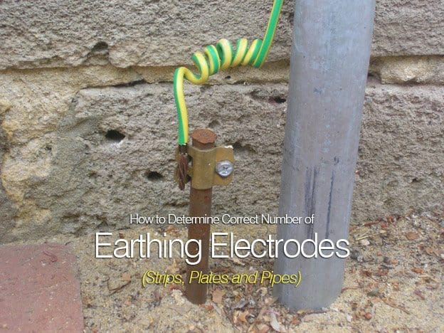
Temporary grounding of normally energized parts with ground rod and earth wire clamp
When personnel work on high-voltage electric structures or equipment, any conductive bodies should be grounded as a measure of safety.
The usual grounding method is to attach a flexible insulated copper cable with a ground clamp or lug on each end. These flexible jumpers require periodic inspection and maintenance. For cable connections to clamps, welded terminations (either a welded plain stud or a threaded silicon bronze stud welded to the conductor end) will provide a secure, permanent connection.
The clamp or lug is solidly connected to ground, then the other clamp is attached to the cable being grounded.
Resource: Practical Grounding, Bonding, Shielding and Surge Protection – G. Vijayaraghavan; Mark Brown; Malcolm Barnes
(Get this book at Amazon)
