Arrangements of LV Utility Distribution Networks (photo by Steve Ives @ Flickr: Street in Haddington, Philadelphia, PA, US)
Continued from the previous part: Arrangements of LV Utility Distribution Networks (1)
The consumer-service connection
In the past, an underground cable service or the wall-mounted insulated conductors from an overhead line service, invariably terminated inside the consumer’s premises, where the cable-end sealing box, the utility fuses (inaccessible to the consumer) and meters were installed.
A more recent trend is (as far as possible) to locate these service components in a weatherproof housing outside the building.

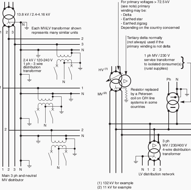
Fig. C4: Widely-used American and European-type systems
Note: At primary voltages greater than 72.5 kV in bulk-supply substations, it is common practice in some European countries to use an earthed-star primary winding and a delta secondary winding. The neutral point on the secondaryside is then provided by a zigzag earthing reactor,the star point of which is connected to earth through a resistor.
Frequently, the earthing reactor has a secondary winding to provide LV3-phase supplies for the substation. It is then referred to as an “earthing transformer”.
A MCCB - moulded case circuit breaker which incorporates a sensitive residual-current earth-fault protective feature is mandatory at the origin of any LV installation forming part of a TT earthing system.
The utility/consumer interface is often at the outgoing terminals of the meter(s) or, in some cases, at the outgoing terminals of the installation main circuit-breaker (depending on local practices) to which connection is made by utility staff, following a satisfactory test and inspection of the installation.
A typical arrangement is shown in Figure C5.

Fig. C5: Typical service arrangement for TT-earthed systems
A further reason for this MCCB is that the consumer cannot exceed his (contractual) declared maximum load, since the overload trip setting, which is sealed by the supply authority, will cut off supply above the declared value. Closing and tripping of the MCCB is freely available to the consumer, so that if the MCCB is inadvertently tripped on overload, or due to an appliance fault, supplies can be quickly restored following correction of the anomaly.
In view of the inconvenience to both the meter reader and consumer, the location of meters is nowadays generally outside the premises, either:
- In a free-standing pillar-type housing as shown in Figures C6 and C7
- In a space inside a building, but with cable termination and supply authority’s fuses located in a flush-mounted weatherproof cabinet accessible from the public way, as shown in Figure C8
- For private residential consumers, the equipment shown in the cabinet in.

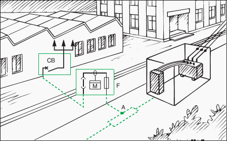
Fig. C6 : Typical rural-type installation
In this kind of installation it is often necessary to place the main installation circuit-breaker some distance from the point of utilization, e.g. saw-mills, pumping stations, etc.

Fig. C7: Semi-urban installations (shopping precincts, etc.)
The main installation CB is located in the consumer’s premises in cases where it is set to trip if the declared kVA load demand is exceeded.

Fig. C8: Town centre installations
The service cable terminates in a flushmounted wall cabinet which contains the isolating fuse links, accessible from the public way. This method is preferred for esthetic reasons, when the consumer can provide a suitable metering and main-switch location.

Fig. C9: Typical LV service arrangement for residential consumers
Figure C5 is installed in a weatherproof cabinet mounted vertically on a metal frame in the front garden, or flush mounted in the boundary wall, and accessible to authorized personnel from the pavement.
Figure C9 shows the general arrangement, in which removable fuse links provide the means of isolation.
For example electronic metering can also help utilities to understand their customers’ consumption profiles.
In the same way, they will be useful for more and more power line communication and radio-frequency applications as well.
In this area, prepayment systems are also more and more employed when economically justified. They are based on the fact that for instance consumers having made their payment at vending stations, generate tokens to pass the information concerning this payment on to the meters. For these systems the key issues are security and inter-operability which seem to have been addressed successfully now.
The attractiveness of these systems is due to the fact they not only replace the meters but also the billing systems, the reading of meters and the administration of the revenue collection.
Resource: Electrical Installation Guide 2009 – Schneider Electric